joi, 20 ianuarie 2011

Shaders Part III: Need a map?

In this (rather long) post, we're going to discuss textures, and a couple of techniques that use them. We're also going to take a look at how texture units(remember those?) work. First off, a texture is usually considered as an array of data(1D textures are uni-dimensional, while 2D textures and volume textures are 2D and 3D). In general, a texture object in a 3D API has several attributes, beyond the pure data, and is usually stored in the GPUs memory(you might also see the term 'server memory' or 'server-side memory', because the relationship between a program and the gpu is a client-server one).
One of these attributes is the mapping function. Say we apply a 2D texture to a triangle; every point on the triangle needs to have a corresponding point on the texture. There are several predefined types of mapping(the basic types are sphere, cylinder and plane; you map the texture to one of these surfaces, then project it on your triangle), but we'll just use UV mapping. This means that every vertex has a UV value(two floats: u and v, each in the [0;1] interval), which are then linearly interpolated for each pixel( (0;0) usually corresponds to the upper-left textel, and (1;1) to the down-right one; a textel is a point on a texture). Another attribute defines what happens outside the [0;1] range; the texture coordinates can be clamped or wrapped, or even mirrored.
The last texture attributes we'll discuss are the minification and magnification filters. To understand what they do, let's imagine an arbitrary UV mapped primitive. In the ideal case, the primitive will be at a moderate distance from the viewer, so each pixel on the screen will correspond to a textel in texture space. Now consider that the primitive comes closer to the camera; each textel will map to several pixels, so we need to somehow do this mapping. This is called magnification. Minification is the exact opposite: when the primitive is far away, each pixel on screen maps to several textels. Both these issues are sampling issues, and the theory behind this is far beyond the scope of this post, but I'll simply state an important result in sampling theory, namely the Nyquist-Shannon theorem. This states that in order to correctly sample a (band limited) signal, you need to use a sampling frequency at least twice as high as the highest frequency in the signal. If you don't do this, high frequencies in the input signal, can masquerade as low frequencies in the output signal(they become 'aliases', hence the name anti-aliasing). This is important for us because mapping textels to pixels is actually a sampling problem; our texture is the signal, and we need to sample it at some fixed points(which are our screen-space pixels). Consider a chess-board like texture; one pixel black and all it's neighbors white. The frequency is 1/2. In order to avoid aliasing, we need to sample it at at least twice that, namely 1 pixel per textel. Now, in the case of magnification, this is satisfied, so we won't see aliasing, but in the case of minification(remember, more than one textel per pixel, hence less than one pixel per textel), aliasing will occur.
Let's treat the relatively simpler case of magnification first: we have several options to get each pixel's color. The simplest one is to use the color of the nearest textel for each pixel(this is also called a nearest neighbor filter, or a box filter). Both sampling theory and practice tell us that this is a poor choice(textures tend to look blocky, and severe temporal aliasing may occur; this means that the textel to pixel mapping greatly changes with viewer position). The widely adopted choice in graphics is bilinear interpolation(this stands for 2D textures; each pixel's color is a linear function of the two nearest neighbors on the x axis and the two nearest neighbors on the y axis(in texture space)). Bilinear interpolation has it's problems, but it gives decent results, and is implemented in hardware.
The problem of minification is a bit trickier, because the Nyquist-Shannon theorem is not satisfied with a simple bilinear filter. This means aliasing would occur(actually both temporal and spatial aliasing occur). The solution used to fix this is mip-mapping. Think about it this way: in order to satisfy the Nyquist-Shannon theorem, we would need a texture that doesn't present high frequencies. This is equivalent to passing the texture trough a low-pass filter(in graphics, this is called a blur filter).So, instead of storing just the texture map, we also store down-sampled versions it (this down-sampling can be achieved trough several filters; the simplest method is to use bilinear interpolation). Now we need to find the two mip levels closest to covering one pixel per textel, and interpolate between them. The metric usually used involves calculating the textel/pixel ratio over the X and Y axis(in texture space), and choosing the mip levels accordingly(the mip level is chosen so that the highest of the two ratios is under 1). Problems will arise when looking at a texture at a grazing angle(an unnecessarily high mip level will be used, so the texture will be blurred). Anisotropic filtering ameliorates this by choosing a mip level corresponding to the lower ratio, and taking extra samples along the other axis. On a side node, mip mapping is generally available in hardware for 1D, 2D and, with some limitation 3D textures, and the mip levels can be specified manually(this only works for texture reads in the pixel shader).
Now that we've seen how textures work, it's time to put them to some use. We're going to start off with specular maps, go trough normal mapping and parallax mapping, and finish with environment mapping.
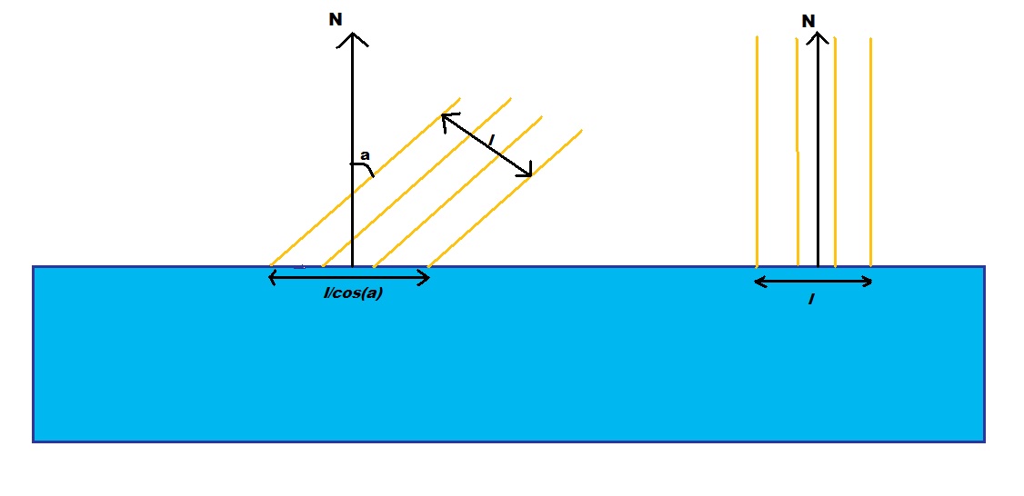
Like I said, we'll start with specular maps. Remember the exponent in the specular term of the Phong lighting equation? It measures the shininess of a surface. Now, imagine a piece of rusty iron, some parts of it are rustier, and hence less reflective, while others may be a lot shinier. First for our actual map:


The vertex shader code is exactly the same as for the diffuse mapping in part I, so I'll only post the pixel shader code(it's based on the code for per-pixel lighting):

float4 Ambient;
float4 matColor;
float4 lightColor;
sampler2D SpecMap;


struct PS_INPUT{
   half2 TexCoord  : TEXCOORD0;
   float3 Normal   : TEXCOORD1;
   float3 View     : TEXCOORD2;
   float3 Light    : TEXCOORD3;
  
};
float4 ps_main(PS_INPUT Input) : COLOR0
{  
   float roughness = 255*(tex2D(SpecMap,Input.TexCoord).r);
   float4 specular = lightColor *     pow(max(0,dot(normalize(Input.Light),
                        reflect(normalize(Input.View), normalize(Input.Normal)))),roughness);
   return( matColor *(Ambient + lightColor * max(0,dot(normalize(Input.Light),normalize(Input.Normal)))) +specular);  
}

Instead of reading our 'roughness' from the application side, we read it from a texture(and scale it with 255, since the sampler retrieves a value between 0 and 1). As we can see, we use the red channel from the texture map, but we might as well have used green or blue. Here is the result(applied on a red disc):
 
This is all pretty simple, so I'll go right to normal mapping. Let's start with the per-pixel lighting shader. We find the normal at each fragment by interpolating the normals at each vertex. This works perfectly well for flat surfaces, but fails to represent any surface detail on the object. To do this we'll store the normals at each point in a map(this is cleverly called normal mapping). Normal maps are used to represent details larger than one pixel(if they were smaller, they'd be represented in the specular exponent of the surface), but smaller than a triangle(if they were larger, we would add geometry). The main issue here is that the normal map stores the normal relative to the surface, so we can't work in world, view or even object space. We need to work in something called tangent space(because it's formed from the tangent, the normal, and the bitangent(sometimes incorrectly called binormal). The tangent we can get from our stream map(simply add a tangent entry); we already have the normal, and the bitangent is the cross product of the two. In order to transform a vector from world space to a space given by it's versors(a versor is a unit length vector in the direction of an axis), we need to project it on the three versors. So v in world space would be (v dot Tangent, v dot Bitangent, v dot Normal). Our vertex shader transforms the Light and View vectors to tangent space, and forwards the texture coordinates:

float4x4 matViewProjection;
float4x4 matViewInverse;
float3 lightPos;
float4 vViewPosition;
struct VS_INPUT
{
   float4 Position : POSITION0;
   half3 Normal    : NORMAL;
   half3 Tangent   : TANGENT;
   half2 Texcoord  : TEXCOORD0;
  
};

struct VS_OUTPUT
{
   float4 Position : POSITION0;
   half2 TexCoord  : TEXCOORD0;
   half3 Light     : TEXCOORD1;
   half3 View      : TEXCOORD2;
  
  
};

VS_OUTPUT vs_main( VS_INPUT Input )
{
   VS_OUTPUT Output;
   half3 BiTangent = cross(Input.Tangent,Input.Normal);
  
   Output.Position = mul( Input.Position, matViewProjection );
  
  
   half3 wLight = Input.Position.xyz - lightPos;
   Output.Light.x = dot(Input.Tangent, wLight);
   Output.Light.y = dot(BiTangent, wLight);
   Output.Light.z = dot(Input.Normal, wLight);
  
   half3 wView = Input.Position.xyz - matViewInverse[3].xyz;
   Output.View.x  = dot(Input.Tangent, wView);
   Output.View.y  = dot(BiTangent, wView);
   Output.View.z  = dot(Input.Normal, wView);
  
 
   Output.TexCoord = Input.Texcoord;
   return( Output );
  
}

The pixel shader is even simpler, the only difference from per pixel lighting is that it doesn't read the normal from the input, but from a texture.

 half3 Normal = normalize(2*tex2D(BumpMap,Input.TexCoord).xyz-1);

Now you just have to add the texture objects for the diffuse, and normal map. Here are the ones I've used, and the end result(they aren't power of two textures, so they're not really recommended for a real application). The normal map is generated using nvida's texture tool. Don't worry about the transparent normal map, we'll be using the alpha channel for paralax mapping.


Normal mapping has it's limits. The most important is that it fails to impress at grazing angles. Another is that it can generate noise when the object is seen from a distance(when the details in the normal map become smaller than a pixel). However it's a cheap way of giving detail to a surface.
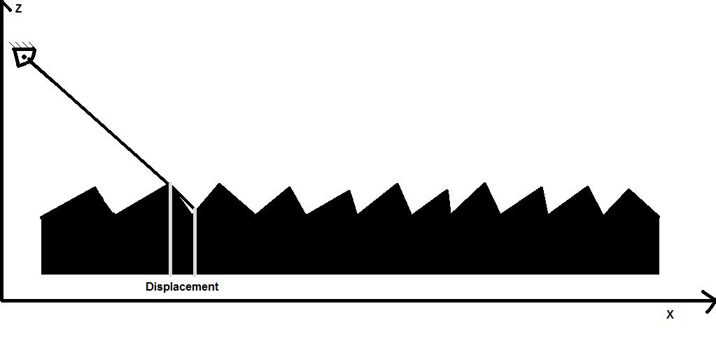
Now on to parallax mapping. Take a look out your window, and find a tree. Put your finger in front of your eye so that it covers the tree. Now move your head, without moving your finger, and it won't cover the tree anymore. That's called parallax. Parallax mapping supplies the height of each pixel, and displaces the texture map based on that height and the view vector(in the case of your tree, the distance from your finger to the tree is the equivalent of the depth). We'll apply both parallax and normal mapping in the same shader, with the height map stored in the alpha channel. Take a look at the image below(as before, sorry for the poor quality art):
As you can see(I hope), the displacement is (depth * x/z,depth*y/z), where depth is, well, the depth stored in the height map(I know, this is a bit confusing) and x, y, z are the components of the view vector. This little equation has a slight issue: when z approaches 0, the displacement tends towards infinity, and since only the fractional part of the tex coords are used, that just results in noise. So we'll sacrifice some physical accuracy for good looks. Now for the actual implementation, I've added 2 new variables, namely a height scale factor( I used a value of 80), and the size of the texture(this is used so that the displacement is the same, in pixels, regardless of texture size). The two definitions, and the modified lines in the pixel shader follow:

float2 texSize;
float maxHeight;

float4 ps_main(PS_INPUT Input) : COLOR0

   half3 height = (1-(tex2D(BumpMap,Input.TexCoord).w));
   half2 texcoord = Input.TexCoord + height*(maxHeight/texSize)*normalize(Input.View).xy;
  ...
}
I won't post a picture with the result, since you need to move the camera to truly see the effect.
Now for the last section of this rather lengthy post: Environment mapping. Consider the proverbial knight in shining armor, just before he rescues the princess. He's probably in a forest, or a dungeon, or whatever, his shiny armor reflecting the trees/corridors/etc. That reflection effect is rather cool, and that's what EM is about(and the forest was actually meant to explain the name). To achieve reflections, we render our environment in a special kind of map, and calculate the reflections at each pixel based on that map. We're only going to use cube maps, which are basically 6 textures arranged on the face of a cube. We can index cube maps using a vector, and we get the texture value at the intersection of that vector with the cube(that's rather convenient considering our application). As a side note, cube maps were used to normalize a vector: you'd have a cube map with the normalized direction at each textel(so we'd index it using a non-normalized vector, and get a value that is our normalized vector). This is actually pretty slow on modern hardware, so I only pointed it out for reference. There are other types of environment maps available besides cubes: both sphere maps and paraboloid maps have seen some use, but I won't cover those here.
Before we start coding, we need to set up our cubemap. We'll use a static one(that means we won't actually be rendering into it), that luckily comes with Render Money. Add a new texture->cube map->snow(also add the texture object to your rendering pass). We'll be working in world space, so the vertex shader is really basic(we only need the view vector):

float4x4 matViewProjection;
float4x4 matViewInverse;

struct VS_INPUT
{
   float4 Position : POSITION0;
   half3 Normal   : NORMAL;
  
};

struct VS_OUTPUT
{
   float4 Position  : POSITION0;
   float3 Normal  : TEXCOORD0;
   float3 View     : TEXCOORD1;
  
  
};

VS_OUTPUT vs_main( VS_INPUT Input )
{
   VS_OUTPUT Output;
   Output.Position = mul( Input.Position, matViewProjection );
   Output.Normal = Input.Normal;
   Output.View  = Input.Position.xyz - matViewInverse[3].xyz;
   return( Output );
  
}
The pixel shader simply indexes the cubemap with the reflection of the view vector by the normal; the samplerCUBE simply samples a cube map:

samplerCUBE Env;

struct PS_INPUT{
   half3 Normal  : TEXCOORD0;
   half3 View     :  TEXCOORD1;
};
float4 ps_main(PS_INPUT Input) : COLOR0
{  
     return(texCUBE(Env, reflect(Input.Normal,normalize(Input.View))));
}

And for the final effect(I used a teapot instead of the earlier disc):
This only scratched the surface of environment mapping, and I'll be writing a post all about it(especially covering the issue of glossy reflections, because our current technique only creates perfect reflections). I really hope you enjoyed this post, as it's a very important topic, and, as always, if you have any questions, or if I wrote something stupid, feel free to comment.

joi, 25 noiembrie 2010

Shaders Part II: Let there be light!

Lighting is a very important part of graphics. Actually, one of the main purposes for shaders was allowing the implementation of arbitrary lighting models. We'll talk more about lighting models in a future post, but for now let's start with something really simple. Fire up Render Monkey and create a default DirectX effect. You should have a red sphere.
In the model we're going to use, we differentiate 3 components to the light contribution. First there's ambient light, which approximates light that bounces many times off other objects before reaching our pixel.Consider a simple experiment: put your hand in front of a light source, in a dark room. The shadow your hand casts on the wall isn't perfectly black; that is what we're approximating with ambient light. Then there's diffuse light, which enters our object, bounces several times inside the object, and is then re-emitted. This component is strongly influenced by the object's color. Finally there's specular light, which bounces directly off the object's surface. This component is usually only influenced by the light source's color(metals are an exception to this).
To begin with, we're going to do our lighting computations per-vertex(this means we evaluate the lighting equation for each vertex and interpolate the results). Oddly enough, we'll start with the pixel shader, which needs to take a color from the vertex shader and output it to the screen:

float4 ps_main(float4 color:COLOR0) : COLOR0
{  
   return( color);
}

This should be fairly easy to understand, so we'll move along. We should now add an ambient component, so let's create a variable for it's color. Right click the root node->Add Variable->Color. Rename it to Ambient, or whatever makes sense to you. Now for the vertex shader:

float4x4 matViewProjection;
float4 Ambient;
struct VS_INPUT
{
   float4 Position : POSITION0;
  
};

struct VS_OUTPUT
{
   float4 Position : POSITION;
   float4 Color    : COLOR;
  
};

VS_OUTPUT vs_main( VS_INPUT Input )
{
   VS_OUTPUT Output;
  
   Output.Position = mul( Input.Position, matViewProjection );
   Output.Color = Ambient;
   return( Output );
 }

All we did was to make the object the same color as our ambient light. Now here's where things get interesting: As I previously said, diffuse lighting models the contribution of light that enters the object surface and scatteres, re-exiting nearby(in this context, nearby means the same pixel). This is also called local sub-surface scattering(as opposed to global subsurface scattering, which may be used to model materials such as milk, or marble, or, more importantly, skin). We need to find the amount of light that gets to the viewer from our pixel, as a function of the ammount of light that gets to the pixel(this is also called a BRDF-bidirectional reflectance distribution function; we'll cover them in depth in a future post).

Consider a light source that emmits a known ammount of energy per surface unit(let's call it Li). Take a look at the image bellow(sorry for the poor art).

If our surface is perpendicular on the incoming light, the amount of energy that reaches each surface unit is Li. If the surface is at an arbitrary angle a with the incoming light, the surface that recieves the same ammount of light is 1/cos(a) larger, so each surface unit receives cos(a) more light. Our surface re-emits Kdiff of incoming light(Kdiff depends on wavelength, so it will be a RGB vector). The outgoing energy will be Li *Kdiff * cos(a). Cos(a) can be expressed as a dot product between the normalized light vector(pixel position - light position) and our normal.  This is usually called a Lambertian term. Now for some code; first add normals to the stream map. Next add a new float3 variable for the light's position(diffuse lighting depends on the light's and our point's position, but not on the viewer's). Now import both the normals and the light's position in the vertex shader.

float4 lightPos;
struct VS_INPUT
{
   float4 Position : POSITION0;
   float3 Normal   : NORMAL;  
};


Now modify the color output line to:

Output.Color = Ambient + dot(normalize(lightPos-Input.Position.xyz),Input.Normal);


The dot color  between two normalized vectors is equal to the value of the cosine between the two vectors. The normal is already normalized, but we need the normalized light vector. This is computed as the difference between the light's position and our point's position(in this case we work in world space, that's why we use the input position; we can work in any convenient space, as long as all vectors are in that space). 
We still have a slight problem, the color on the dark side of our sphere should be the ambient light's color, but it's currently perfectly black. The reason for this is that our dot product can actually become negative(and it does, when the normal and the light vector at an angle higher than Pi/2), which actually darkens our color. We need to clamp it to 0, so the line becomes:
Output.Color = Ambient + max(0,dot(normalize(lightPos-Input.Position.xyz),Input.Normal));

We still haven't taken the object's or the light's color into account. Add a new color variable for the light's color, and one for the ball's color. The material's color affects both the ambient term and the diffuse term, but the light's color only affects the diffuse term(remember, the ambient term is an approximation of all lights in the scene). Our output line should look something like this:

Output.Color = matColor * (Ambient + lightColor * max(0,dot(normalize(lightPos-Input.Position.xyz),Input.Normal)));


Now to add some specular light. A specular term models the light that bounces off the surface of the object and makes it's way to the eye. On a perfectly flat surface, a point light would cast a single ray of light to the viewer(that ray makes the same angle with the normal as the viewer does).
However, no real surface is perfectly flat. Each surface presents some irregularities at a sub-pixel level(this is called microgeometry). So, in effect, more than one light ray reaches the viewer:
The Phong lighting model considers that the ammount of light that reaches the viewer by direct reflection is proportional to the (clamped)cosine of the angle between the light vector and the reflected(around the normal) view vector, raised to a positive power. The angle in that equation is actually a measure of how far we are from an ideal reflection angle. The power to which we raise that cosine is a measure of how rough the surface is(for a roughness of infinity the surface behaves like it is perfectly flat). First we'll need to know the viewer's position. The view matrix contains a translation equal to minus the camera's position, so all we need is the inverse view matrix. Luckily for us, Render Monkey can do that. Right click the root node->Add variable->matriz->Predefined -> matViewInverse. We should also add a variable for the specular exponent(I called it roughness). Now go ahead and import it into the vertex shader. Our output line, based on the Phong lighting model becomes:

float4 specular = lightColor * pow(max(0,dot(normalize(Input.Position.xyz -lightPos),
                        reflect(normalize(Input.Position - matViewInverse[3]).xyz, Input.Normal))),roughness);
   Output.Color = matColor * (Ambient + lightColor *max(0,dot(normalize(lightPos-Input.Position.xyz),Input.Normal))) + specular;

I've separated the specular component, so that the equation is easier to read. There is a slight catch: this equation doesn't model metals very well. With most materials, the specular component is independent of material color. Good conductors behave differently. First, no diffuse lighting is generally present, because light doesn't enter a metallic surface. Secondly, the specular component's color depends on the material's color. 
All in all, this is the image you should be seeing at this stage:
This is actually what the fixed function pipeline does, and you can already see it's problems. You can actually distinguish the borders of the sphere's underlying triangles. That's because we calculate the color per vertex and linearly interpolate to get the value at each pixel. So, if the center of the highlight happens to be at a vertex's position, we'll have a strong highlight, but if it's right in the middle of a triangle, we'll have a weak one(or even not at all if the triangle is large enough). The solution is computing our lighting equation for each pixel.First of all, we need to change the output from our vertex shader. Our pixel shader needs the light and view vectors, plus the normals, so that`ll be our output. In this case, we'll be working in world space(and in a real application, you'd need to multiply both position and normals with the model matrix). We'll be outputting the three vectors to TEXCOORD0 to 2 (although you'd think these have to do with texture coordinates, they can actually be used for anything). This is the whole vertex shader code

float4x4 matViewProjection;
float4x4 matViewInverse;
float3 lightPos;
float4 vViewPosition;
struct VS_INPUT
{
   float4 Position : POSITION0;
   float3 Normal   : NORMAL;
   
};

struct VS_OUTPUT
{
  
float4 Position : POSITION0;
  
float3 Light    : TEXCOORD0;
   float3 Normal   : TEXCOORD1;
   float3 View     : TEXCOORD2;
   
};

VS_OUTPUT vs_main( VS_INPUT Input )
{
   VS_OUTPUT Output;

   Output.Position = mul( Input.Position, matViewProjection );
   Output.Light = Input.Position.xyz - lightPos;
   Output.View  = Input.Position.xyz - matViewInverse[3].xyz;
   Output.Normal = Input.Normal;
   
   return( Output );
   
}


In this case the pixel shader does all the work. The computations are the same as earlier, but we use the interpolated view vector, light vector and normal. 


float4 Ambient;
float4 matColor;
float4 lightColor;

float roughness;

struct PS_INPUT{
   float3 Light : TEXCOORD0;
   float3 Normal   : TEXCOORD1;
   float3 View     : TEXCOORD2;
};
float4 ps_main(PS_INPUT Input) : COLOR0
{  
  
   float4 specular = lightColor * pow(max(0,dot(normalize(Input.Light),
                        reflect(normalize(Input.View), normalize(Input.Normal)))),roughness);
   return( matColor * (Ambient + lightColor * max(0,dot(normalize(Input.Light),normalize(Input.Normal)))) +specular);  
}


I've also attached the final image, and I'll try adding the render monkey project, when I can find a place to host it.


duminică, 21 noiembrie 2010

Shaders Part I: Hello World!

This post is the first in a series involving shader programming. Shaders are programs executed by the GPU. Vertex Shaders are executed for each vertex that goes trough the graphics pipeline, Geometry Shaders are executed for each primitive(triangle, line, etc), and pixel shaders(OpenGL calls them fragment shaders) are executed for each fragment. This will become clearer once you see some code. We'll be using AMD's Render Monkey for writing shaders, since it allows us to focus on the shaders themselves, and not on the application code(I'll try to cover that in later posts). Go ahead and download Render Monkey from here. After you download and install it, fire it up. You should see something like this:

Right click on Effect Workspace -> Add Effect Group -> Effect Group W/ DirectX Effect
You should now see something like this:

 Now you have a red ball..isn't that exciting? Well, not really, but it is a start. Let's have a look at what's involved in rendering this red ball. First off, look at the tree panel on the left, where you can see 3 variables and a rendering pass. The first variable is the ViewProjection Matrix, and it's supplied by the application code(in this case by Render Monkey); variables that are set by the application, are called uniform(in this case it's actually declared as a global variable). The next variable is named stream mapping and it's used to correlate model data to vertex shader inputs. The third variable is your model, which should be pretty self explanatory(you can right click it to change models or coordinate system orientation).
Next we have a rendering pass with a vertex and pixel shader. Shader syntax is very similar to C, so it should look pretty familiar. Keep in mind that conditionals(and loops) are only available in shader model 3 or higher, and even there, they are very slow. The rendering pass also has a reference to our model and to our Stream Mapping(you can recognize that it's a reference by the small arrow icon). You need such references because models and Stream Maps are implicit(you don't use your model's name anywhere in your shader code), so Render Monkey needs to know what to use for that pass.
The vertex shader simply takes every vertex and transforms it by the ModelViewProjection matrix(in this case just the ViewProjection matrix, since in RM object space is actually world space). Let's look at it line by line.

float4x4 matViewProjection;


This line declares the view projection matrix as a 4x4 matrix of floats(most variables in shaders tend to be floating point, so either half(16 bits), float(32 bits), or double(64 bits); you should keep in mind that using halfs is significantly faster on most GPUs) .


struct VS_INPUT
{
   float4 Position : POSITION0;
  
};


This defines our input structure, in this case a 4 float vector. POSITION0 is something called a semantic; it tells the shader compiler to bind an incoming vertex's position to this variable. 

struct VS_OUTPUT
{
   float4 Position : POSITION0;
  
};


Our output looks similar to our input, in that we only write the position. A vertex shader must always write POSITION0, since vertices go trough other stages in the pipeline after the vertex shader. 

VS_OUTPUT vs_main( VS_INPUT Input )
{
   VS_OUTPUT Output;

   Output.Position = mul( Input.Position, matViewProjection );
  
   return( Output );
  
}


Our entry point is called vs_main(this is the main function of the vertex shader, we can have other functions as well), and it takes a VS_INPUT parameter and returns a VS_OUTPUT.  Using structures isn't mandatory, we could also have something like(On a side note, POSITION0 and POSITION are the same thing):


float4 vs_main( float4 Position : POSITION ) : POSITION

The only actual computation in the vertex shader is multiplying the input position by the ViewProjection matrix. The mul function is very flexible, you can multiply two matrices or a matrix and a vector, as long as they are properly sized. 

On to the pixel shader:

float4 ps_main() : COLOR0
{  
   return( float4( 1.0f, 0.0f, 0.0f, 1.0f ) );
  
}
In this case, the pixel shader takes no parameters(the ball is uniformly red), and returns a color(the pixel shader has to write COLOR0). 

Let's try changing our model, and adding a texture.  First, right click the model node(not the reference to it), go to Change Model, and choose Cracked Quad.3ds. Now we need some texture coordinates, and to do that, you need to double click the stream mapping and add TEXCOORD to the stream list, like so:
Now we need an actual texture: right click the top node->Add Texture->Add 2D Texture and choose Fieldstone.tga.

We also have to add a texture sampler to our render pass. Right click Pass0->Add Texture Object and select our texture. This links a sampling unit to your texture image. The sampling unit is in charge of, well...sampling the texture(this involves filtering), and you have to know that they are a limited resource(D3D9 GPUs have 16 samplers or more, for example).
Now, let's modify the pixel shader code(btw, I renamed my sampler to Diffuse, Texture0 is pretty non-descriptive for a name).First, we need to add our sampler, as a global variable:
sampler2D Diffuse;
Now we need to add the texture coordinates as an input, so our definition of PS_MAIN becomes:
float4 ps_main(float2 texcoords:TEXCOORD0) : COLOR0
Let's also sample the texture:
float4 diffuse = tex2D(Diffuse, texcoords); 
return( diffuse );
The first argument of the tex2D instruction is the sampler, and the second one is a set of coordinates(for a 2d texture we only need 2 coordinates, but we can also sample 1D textures, 3D textures or cube maps). 
If all went well, you should now see a beige colored model. Now, that doesn't look like our image, so what went wrong? There are two things that could go wrong here: the sampler might not be set up correctly, or the texture coordinates aren't the right ones. The latter is easier to test: just output them to the screen. Change the return line to the following:
return( float4(texcoords,0.0,1.0) ); 
You should now see a black screen; this means our texture coordinates are always (0.0,0.0). That can't be right... The problem is that except for uniform variables, anything that gets to the pixel shader needs to pass trough the vertex shader as well, which doesn't happen with our tex coords. Modify the vertex shader to this:


float4x4 matViewProjection;

struct VS_INPUT
{
   float4 Position : POSITION0;
   float2 texcoord : TEXCOORD;
  
};

struct VS_OUTPUT
{
   float4 Position : POSITION0;
   float2 texcoord : TEXCOORD;
  
};

VS_OUTPUT vs_main( VS_INPUT Input )
{
   VS_OUTPUT Output;

   Output.Position = mul( Input.Position, matViewProjection );
   Output.texcoord = Input.texcoord;
   return( Output );
  
}


This simply forwards the tex coordinates to the pixel shader. You should now see something like this:


Now simply change the return statement in the pixel shader back, and you should have a textured cracked quad.


First Things First

Hi, my name is Radu Andrei, and I'm a Computer Science student. I decided to start this blog because I find it useful to document what I do, and if someone finds my posts useful, all the better. If you happen to find any mistakes in what I post, or you don't understand something, feel free to post a comment, or e-mail me at andrei [d.o.t] radu [shift+2] cti[d.o.t]pub [d.o.t] ro (apparently spam bots have gotten smarter).