In the model we're going to use, we differentiate 3 components to the light contribution. First there's ambient light, which approximates light that bounces many times off other objects before reaching our pixel.Consider a simple experiment: put your hand in front of a light source, in a dark room. The shadow your hand casts on the wall isn't perfectly black; that is what we're approximating with ambient light. Then there's diffuse light, which enters our object, bounces several times inside the object, and is then re-emitted. This component is strongly influenced by the object's color. Finally there's specular light, which bounces directly off the object's surface. This component is usually only influenced by the light source's color(metals are an exception to this).
To begin with, we're going to do our lighting computations per-vertex(this means we evaluate the lighting equation for each vertex and interpolate the results). Oddly enough, we'll start with the pixel shader, which needs to take a color from the vertex shader and output it to the screen:
float4 ps_main(float4 color:COLOR0) : COLOR0
{
return( color);
}{
return( color);
This should be fairly easy to understand, so we'll move along. We should now add an ambient component, so let's create a variable for it's color. Right click the root node->Add Variable->Color. Rename it to Ambient, or whatever makes sense to you. Now for the vertex shader:
float4x4 matViewProjection;
float4 Ambient;
struct VS_INPUT
{
float4 Position : POSITION0;
};
struct VS_OUTPUT
{
float4 Position : POSITION;
float4 Color : COLOR;
};
VS_OUTPUT vs_main( VS_INPUT Input )
{
VS_OUTPUT Output;
Output.Position = mul( Input.Position, matViewProjection );
Output.Color = Ambient;
return( Output );
}
All we did was to make the object the same color as our ambient light. Now here's where things get interesting: As I previously said, diffuse lighting models the contribution of light that enters the object surface and scatteres, re-exiting nearby(in this context, nearby means the same pixel). This is also called local sub-surface scattering(as opposed to global subsurface scattering, which may be used to model materials such as milk, or marble, or, more importantly, skin). We need to find the amount of light that gets to the viewer from our pixel, as a function of the ammount of light that gets to the pixel(this is also called a BRDF-bidirectional reflectance distribution function; we'll cover them in depth in a future post).

Consider a light source that emmits a known ammount of energy per surface unit(let's call it Li). Take a look at the image bellow(sorry for the poor art).
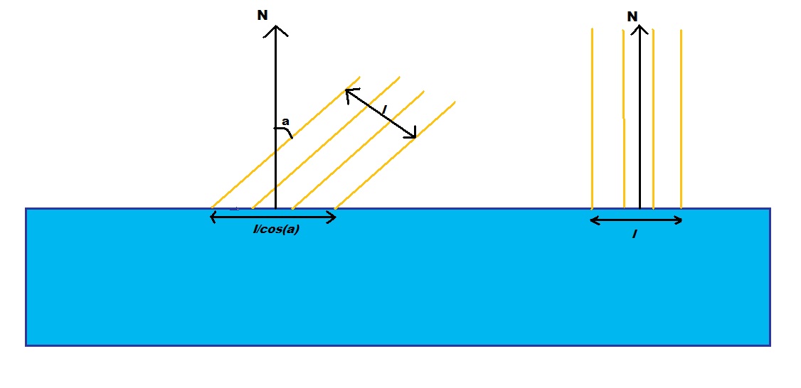
If our surface is perpendicular on the incoming light, the amount of energy that reaches each surface unit is Li. If the surface is at an arbitrary angle a with the incoming light, the surface that recieves the same ammount of light is 1/cos(a) larger, so each surface unit receives cos(a) more light. Our surface re-emits Kdiff of incoming light(Kdiff depends on wavelength, so it will be a RGB vector). The outgoing energy will be Li *Kdiff * cos(a). Cos(a) can be expressed as a dot product between the normalized light vector(pixel position - light position) and our normal. This is usually called a Lambertian term. Now for some code; first add normals to the stream map. Next add a new float3 variable for the light's position(diffuse lighting depends on the light's and our point's position, but not on the viewer's). Now import both the normals and the light's position in the vertex shader.
float4 lightPos;
struct VS_INPUT
{
float4 Position : POSITION0;
float3 Normal : NORMAL;
};
{
float4 Position : POSITION0;
float3 Normal : NORMAL;
};
Now modify the color output line to:
Output.Color = Ambient + dot(normalize(lightPos-Input.Position.xyz),Input.Normal);
The dot color between two normalized vectors is equal to the value of the cosine between the two vectors. The normal is already normalized, but we need the normalized light vector. This is computed as the difference between the light's position and our point's position(in this case we work in world space, that's why we use the input position; we can work in any convenient space, as long as all vectors are in that space).
We still have a slight problem, the color on the dark side of our sphere should be the ambient light's color, but it's currently perfectly black. The reason for this is that our dot product can actually become negative(and it does, when the normal and the light vector at an angle higher than Pi/2), which actually darkens our color. We need to clamp it to 0, so the line becomes:
Output.Color = Ambient + max(0,dot(normalize(lightPos-Input.Position.xyz),Input.Normal));
We still haven't taken the object's or the light's color into account. Add a new color variable for the light's color, and one for the ball's color. The material's color affects both the ambient term and the diffuse term, but the light's color only affects the diffuse term(remember, the ambient term is an approximation of all lights in the scene). Our output line should look something like this:
Now to add some specular light. A specular term models the light that bounces off the surface of the object and makes it's way to the eye. On a perfectly flat surface, a point light would cast a single ray of light to the viewer(that ray makes the same angle with the normal as the viewer does).
We still haven't taken the object's or the light's color into account. Add a new color variable for the light's color, and one for the ball's color. The material's color affects both the ambient term and the diffuse term, but the light's color only affects the diffuse term(remember, the ambient term is an approximation of all lights in the scene). Our output line should look something like this:
Output.Color = matColor * (Ambient + lightColor * max(0,dot(normalize(lightPos-Input.Position.xyz),Input.Normal)));
Now to add some specular light. A specular term models the light that bounces off the surface of the object and makes it's way to the eye. On a perfectly flat surface, a point light would cast a single ray of light to the viewer(that ray makes the same angle with the normal as the viewer does).

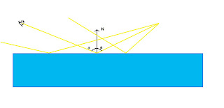
However, no real surface is perfectly flat. Each surface presents some irregularities at a sub-pixel level(this is called microgeometry). So, in effect, more than one light ray reaches the viewer:

The Phong lighting model considers that the ammount of light that reaches the viewer by direct reflection is proportional to the (clamped)cosine of the angle between the light vector and the reflected(around the normal) view vector, raised to a positive power. The angle in that equation is actually a measure of how far we are from an ideal reflection angle. The power to which we raise that cosine is a measure of how rough the surface is(for a roughness of infinity the surface behaves like it is perfectly flat). First we'll need to know the viewer's position. The view matrix contains a translation equal to minus the camera's position, so all we need is the inverse view matrix. Luckily for us, Render Monkey can do that. Right click the root node->Add variable->matriz->Predefined -> matViewInverse. We should also add a variable for the specular exponent(I called it roughness). Now go ahead and import it into the vertex shader. Our output line, based on the Phong lighting model becomes:
float4 specular = lightColor * pow(max(0,dot(normalize(Input.Position.xyz -lightPos),
reflect(normalize(Input.Position - matViewInverse[3]).xyz, Input.Normal))),roughness);
Output.Color = matColor * (Ambient + lightColor *max(0,dot(normalize(lightPos-Input.Position.xyz),Input.Normal))) + specular;
reflect(normalize(Input.Position - matViewInverse[3]).xyz, Input.Normal))),roughness);
Output.Color = matColor * (Ambient + lightColor *max(0,dot(normalize(lightPos-Input.Position.xyz),Input.Normal))) + specular;
I've separated the specular component, so that the equation is easier to read. There is a slight catch: this equation doesn't model metals very well. With most materials, the specular component is independent of material color. Good conductors behave differently. First, no diffuse lighting is generally present, because light doesn't enter a metallic surface. Secondly, the specular component's color depends on the material's color.
All in all, this is the image you should be seeing at this stage:

float4x4 matViewProjection;
float4x4 matViewInverse;
float3 lightPos;
float4 vViewPosition;
struct VS_INPUT
{
float4 Position : POSITION0;
float3 Normal : NORMAL;
};
struct VS_OUTPUT
{
float4 Position : POSITION0;
float3 Light : TEXCOORD0;
float3 Normal : TEXCOORD1;
float3 View : TEXCOORD2;
};
VS_OUTPUT vs_main( VS_INPUT Input )
{
VS_OUTPUT Output;
Output.Position = mul( Input.Position, matViewProjection );
Output.Light = Input.Position.xyz - lightPos;
Output.View = Input.Position.xyz - matViewInverse[3].xyz;
Output.Normal = Input.Normal;
return( Output );
}
In this case the pixel shader does all the work. The computations are the same as earlier, but we use the interpolated view vector, light vector and normal.
float4 Ambient;
float4 matColor;
float4 lightColor;
float roughness;
struct PS_INPUT{
float3 Light : TEXCOORD0;
float3 Normal : TEXCOORD1;
float3 View : TEXCOORD2;
};
float4 ps_main(PS_INPUT Input) : COLOR0
{
float4 specular = lightColor * pow(max(0,dot(normalize(Input.Light),
reflect(normalize(Input.View), normalize(Input.Normal)))),roughness);
return( matColor * (Ambient + lightColor * max(0,dot(normalize(Input.Light),normalize(Input.Normal)))) +specular);
}
I've also attached the final image, and I'll try adding the render monkey project, when I can find a place to host it.

Niciun comentariu:
Trimiteți un comentariu